Editing Tools
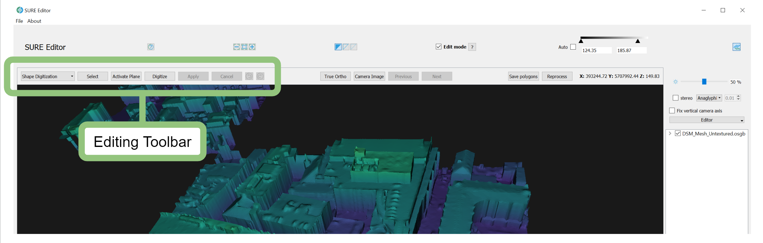
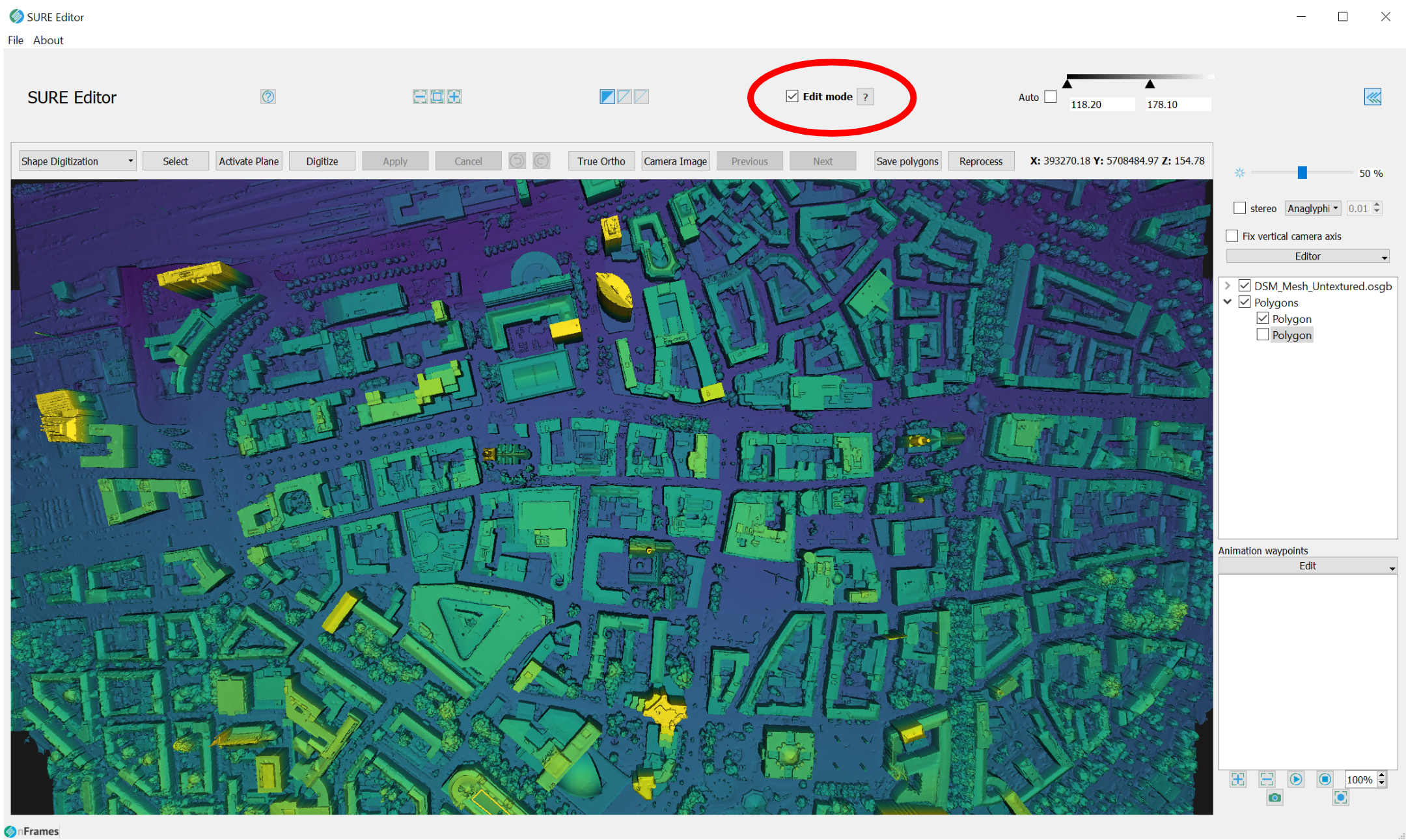
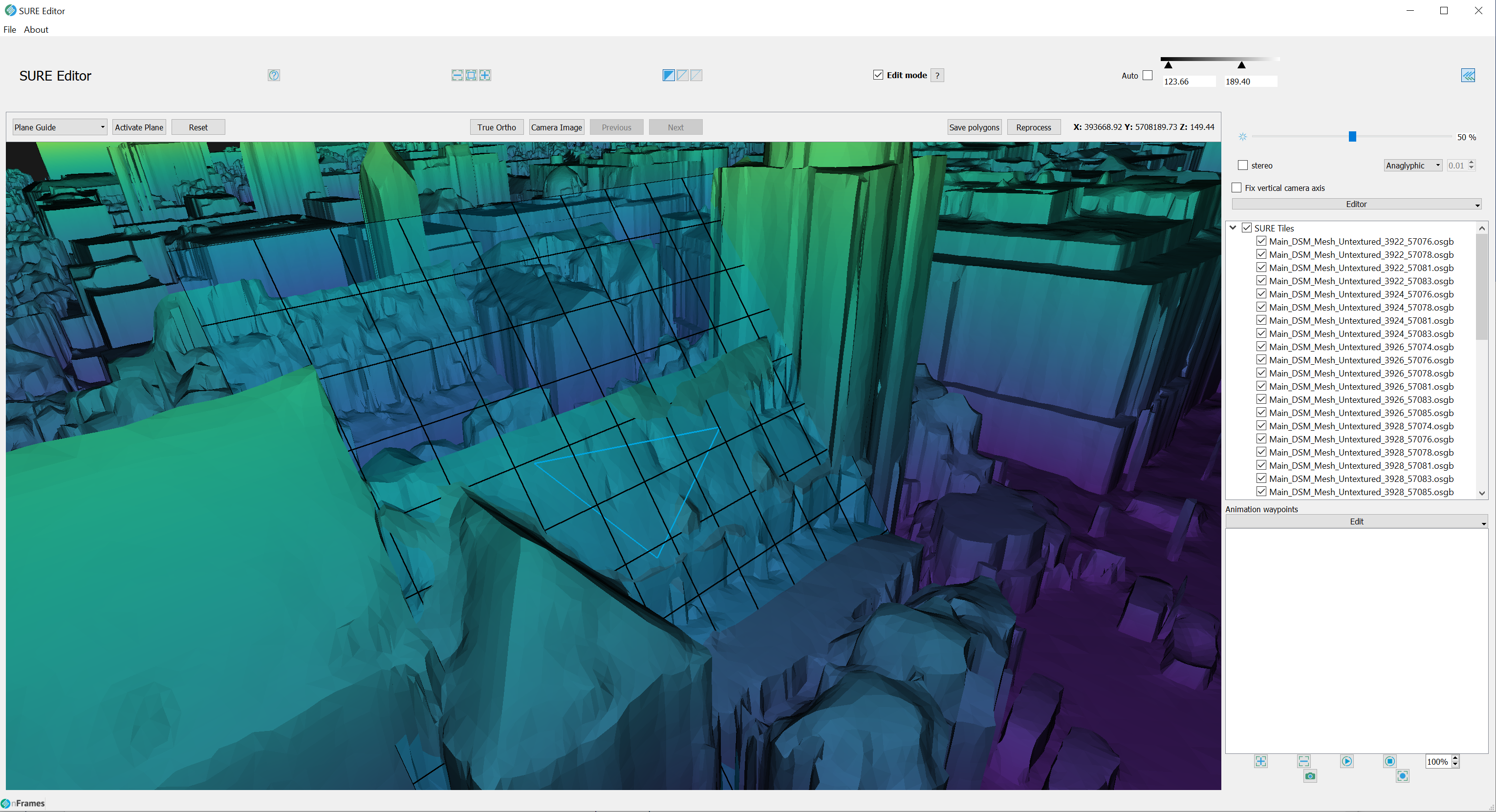
The new SURE Editor has all its editing tools in one place The Editing Toolbar. Located in the top-left corner of the Sure Editor window, these tools enable you to efficiently digitize 3D polygons and perform basic measurements on the DSM Mesh. The Editing Tool Bar has a drop-down menu from where the different editing tools can be quickly activated. Here you can also find commonly used functions such as selecting a polygon, activating (guiding) plane, digitizing a new polygon, applying or canceling the current polygon, and undoing and redoing polygon vertices. To enable these tools please Open A Project and enable the Edit mode:
Now you are ready to start digitizing polygons. There are two tools for creating polygons within the SURE Editor, the Shape Digitization Tools, and The Guiding Plane Tool.
Shape Digitization Tool
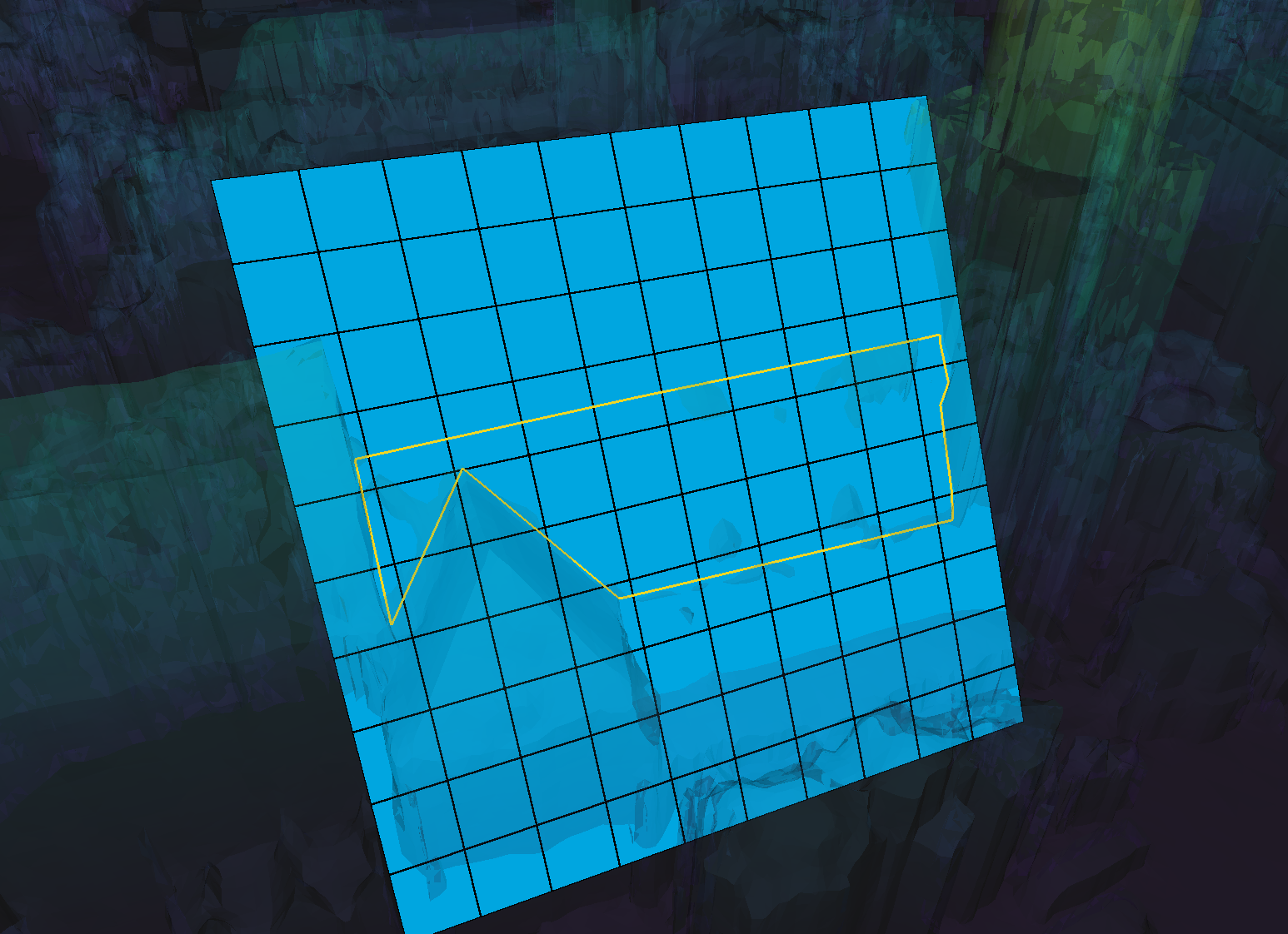
This tool enables you to construct polygons by creating vertices that lie on the surface of the untextured mesh. The following are steps to create a single polygon:
Select the Shape Digitization from the drop-down menu in the Editing Tool Bar
Press 'D' to activate Digitization Tool
Left Click to create new vertex
Ctrl+Z will undo last vertex → same as ‘undo' button on Editing Tool Bar
Ctrl+K will redo last deleted vertex → same as ‘redo’ button on Editing Tool Bar
Esc will clear the active polygon
Right-click to Create/Apply the polygon → same as ‘Apply’ button on Editing Toolbar
Ctrl+S button to save polygons to a shapefile → same as ‘Save Polygons’ button on Processing Toolbar
Ctrl+Q to clear all polygons in the current Editor session **Polygons previously saved do not get deleted from disk
Shapefiles containing 3D polygons can be imported by drag-and-dropping the file into the Editor while in Edit mode
Saving a shapefile will create a new subfolder in your base project with a timecode (e.g. CorrectionShape-19-09-27-14-10-53). This includes a "CorrectionShape.shp" file that contains the digitized and/or uploaded polygons and an "EditedAreaShape.shp" which represents the tiles that are affected by the polygons.
Guiding Plane Tool
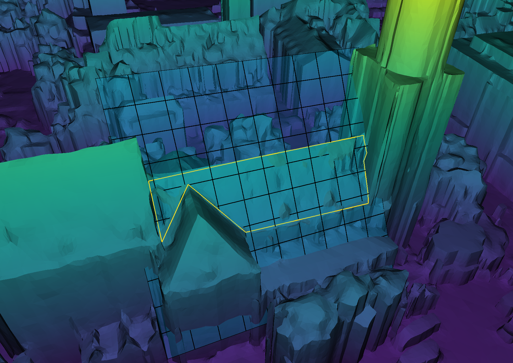
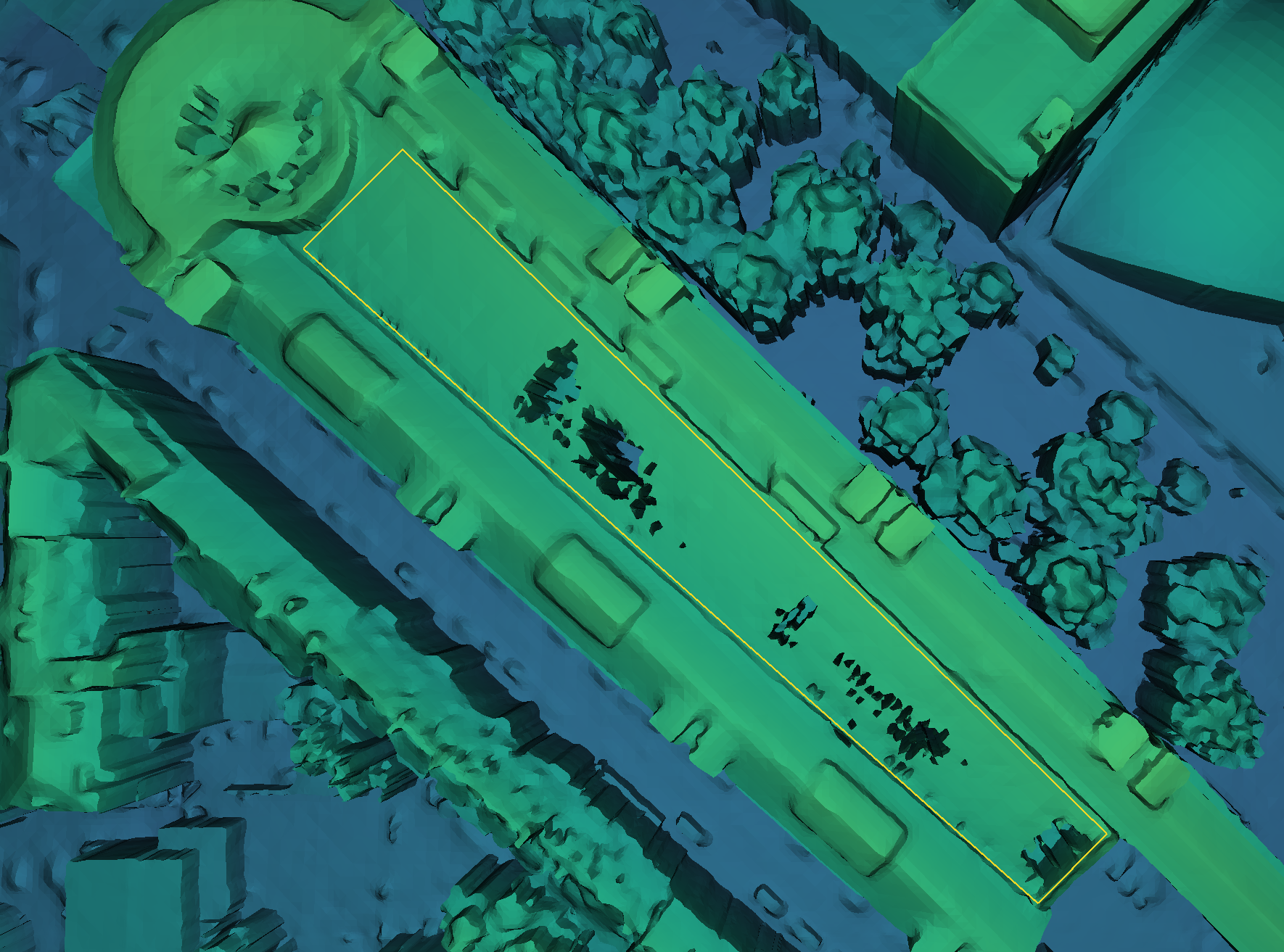
This tool allows drawing a polygon with a height that differs from the current mesh. This is especially useful if a building's rooftop does not extend enough in the True Ortho and appears to be eaten out. The plane is manually defined by specifying 3 points on the DSM Mesh.
To create a guiding plane:
Select Plane Guide from the drop-down menu in the Editing Tool Bar.
Left Click for adding a plane defining point. Setting the second vertex will generate a plane (not fixed yet).
Ctrl+Scroll Wheel for scaling the plane size (the correcting polygon that you want to create must fit within the plane).
Press Esc to clear the current plane.
Left Click a third time to fix the plane in space
Initially, the guide plane will be transparent, which means that it is inactive. Press “P” to activate the plane (the plane will become more opaque, while the mesh turns transparent)
Now you can digitize a correcting polygon on the guide plane
If the guiding plane is inactive, the Shape Digitization tool will sample the vertices of the polygons on the mesh, i.e. using the meshes height as z-value. If the Guiding Plane is active, the Shape Digitization tool will sample points on the plane, i.e. using the plane's height as z-value. You can freely toggle the plane's state (by pressing “P”) while digitizing , resulting in some points being sampled on the mesh and others on the plane.