Mesh Editing Workflow
Motivation
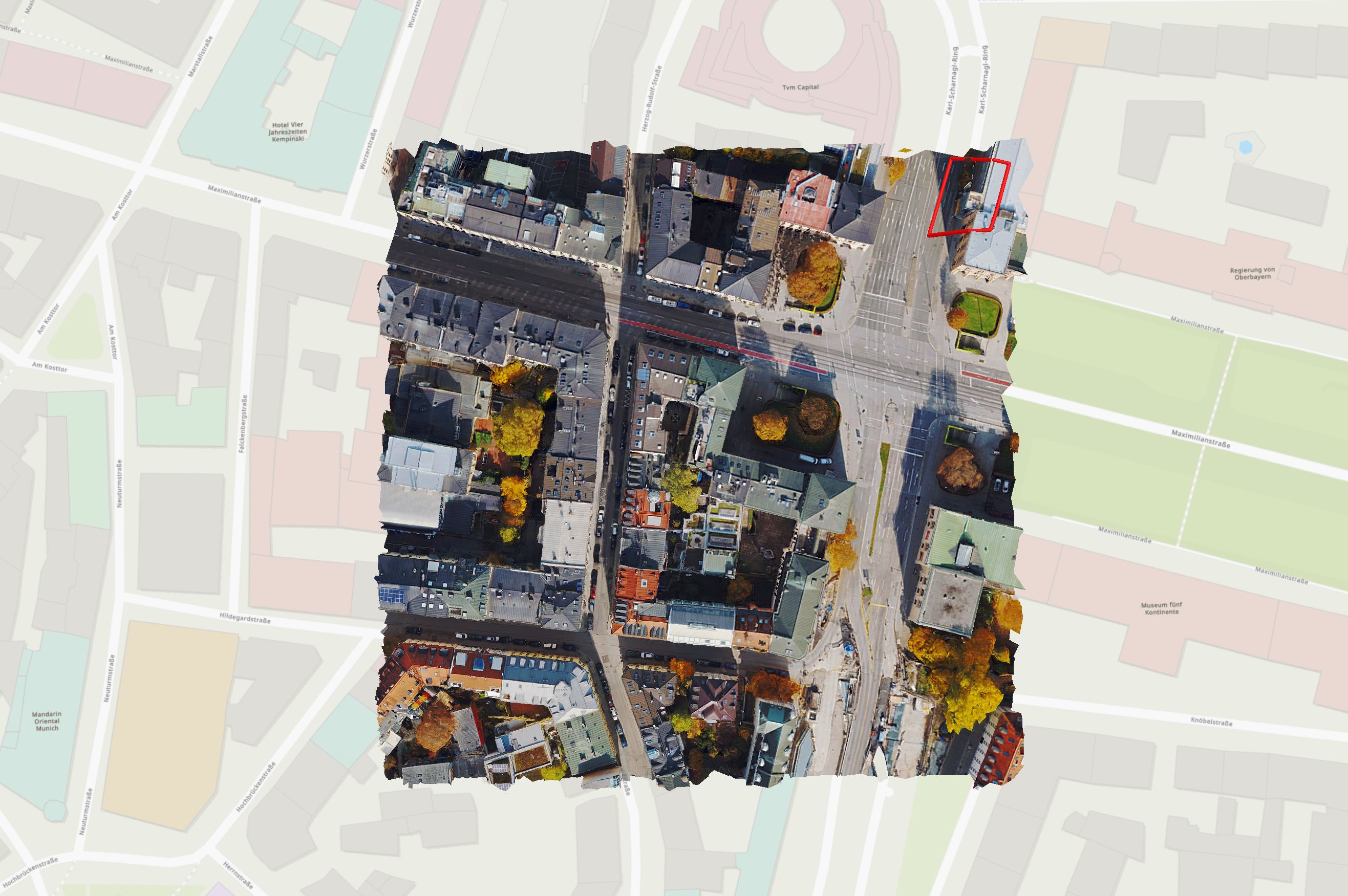
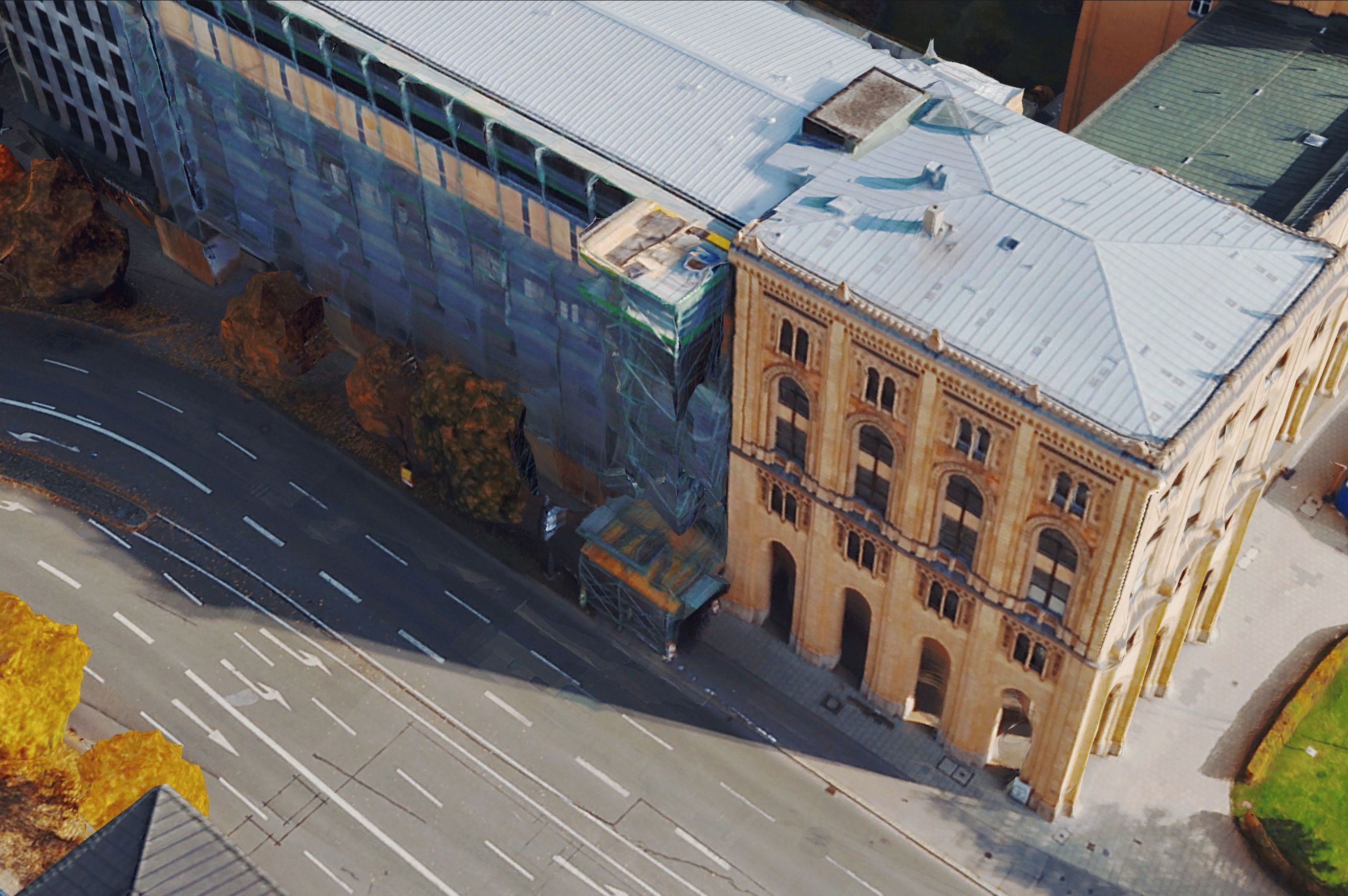
Captured scenes may contain complex structures. Such instances include large reflective or transparent surfaces (e.g. glass facades), urban canyons, objects with intricate geometry (e.g. suspended bridges). High quality input data are of utmost importance, yet cannot always guarantee the absence of incorrect or incomplete surface reconstruction during the meshing process.
The Mesh editing workflow set out below can be used to edit defects and achieve optimal results. Here are some examples of how the Mesh results can be improved through editing:
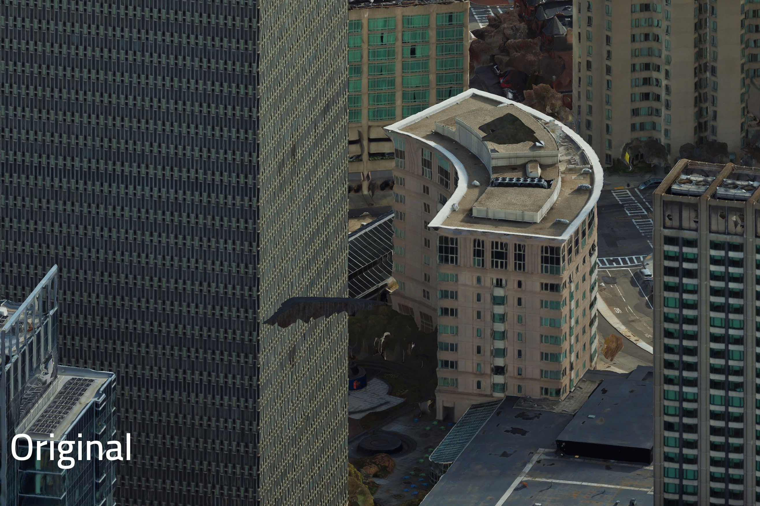
Mesh editing is considered an exceptional intervention, for eliminating severe isolated artifacts or for meeting high quality requirements in selected areas of interest. It is not supposed to be used for mass-scale manual modelling. Overall poor quality results may indicate a systematic problem in the input data or the way in which they have been used in the software. If this is the case, the problems should be addressed at their root cause and not at the stage of the Mesh results.
To verify your results with us, feel free to approach us at support@nframes.com.
Tools in the SURE portfolio facilitate the workflow of editing Mesh sections, reapplying texture and integrating the edited Mesh back into the overall results.
Workflow
Depicted in the diagram below are the components of the workflow and the tools involved in the respective steps.
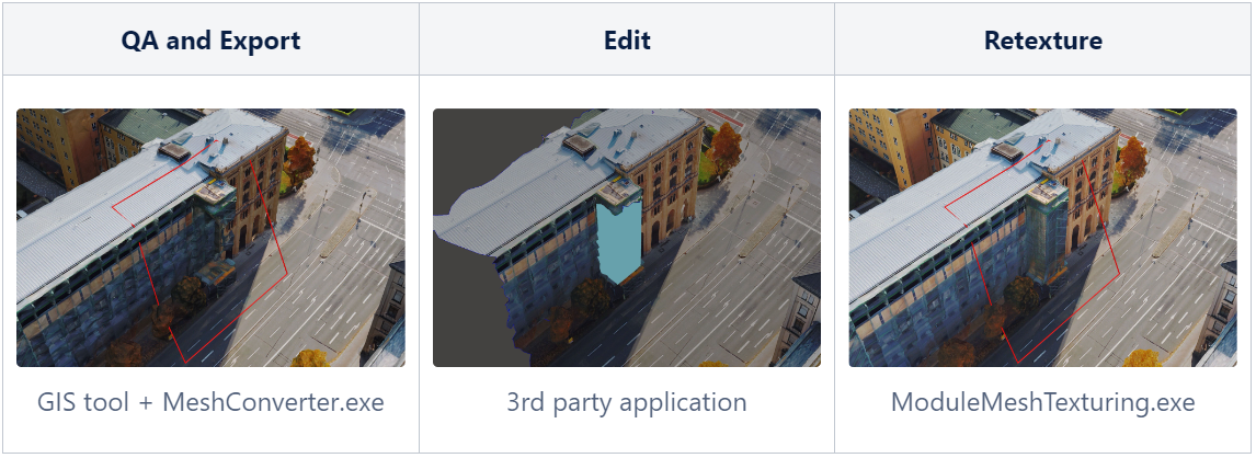
Defects in the Mesh should be indicated with polygons in a shapefile and exported as Edit Units in Local OBJ format.
The actual editing of the Mesh geometry must be performed in a third party tool of the user's choice. Some of these tools are free to use under special licensing schemes. They all support various surface editing operations. Examples include: Meshmixer, Open Flipper, MeshLab, Blender, etc.
After editing, the Edit Units undergo retexturing and then are integrated into a standard textured (LOD) Mesh. The result is then ready for further use (e.g. conversion to supported formats, customer delivery, reperform Mesh Editing, if needed, etc.).
Step-by-step guide
To undertake the following steps a complete SURE Project is required. If some files/folders have been deleted from the project, this workflow may not be possible.
Screenshots / gifs data courtesy: Hexagon
Quality Inspection and Indication of Artifacts
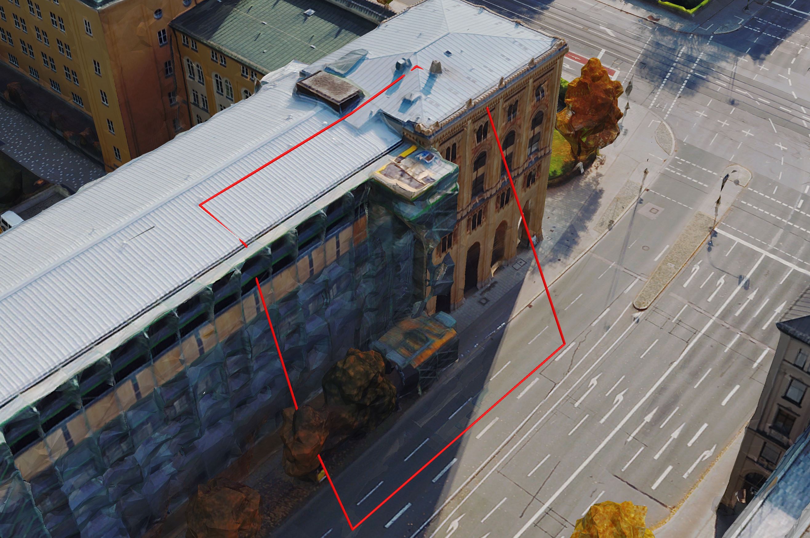
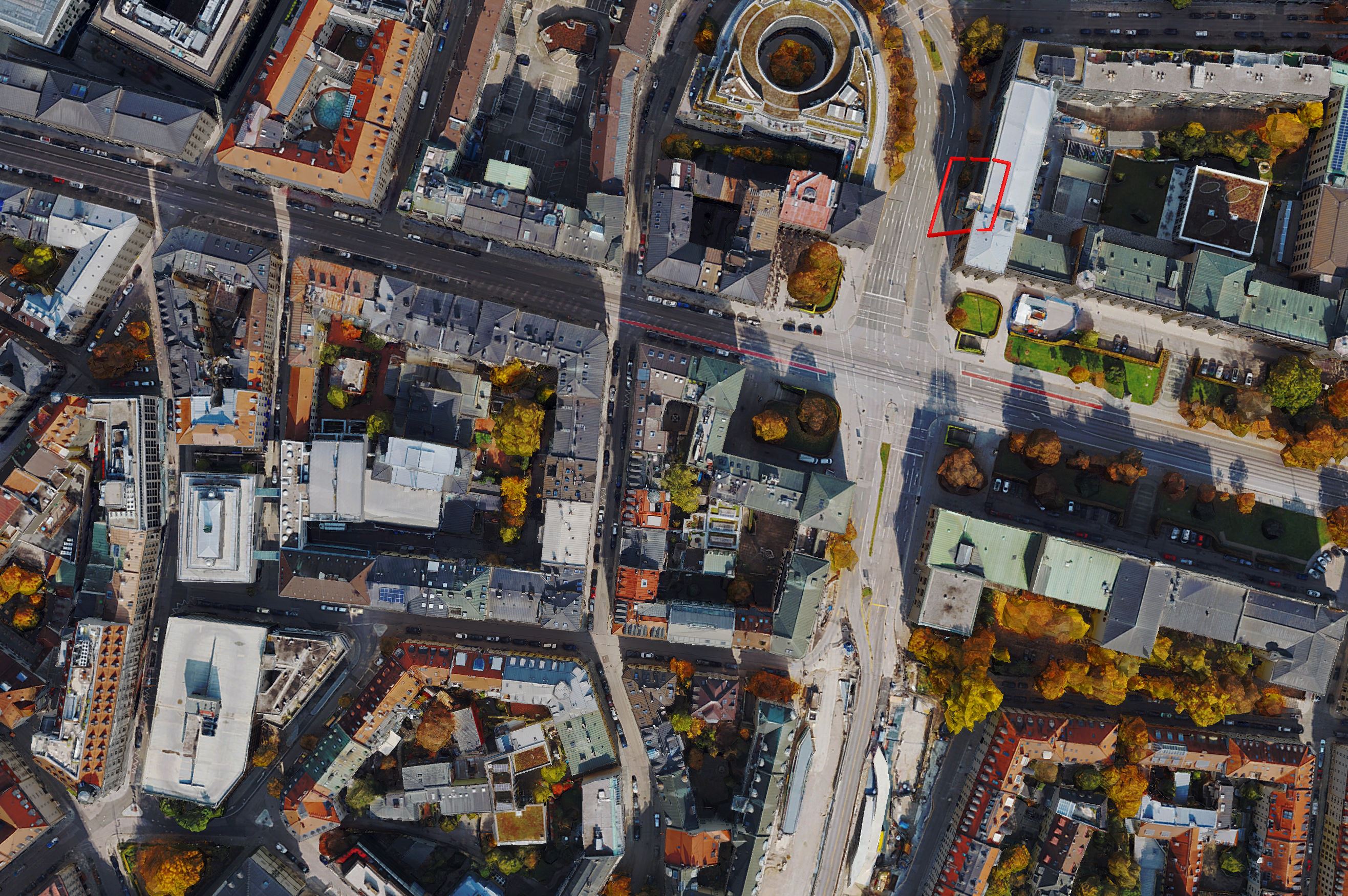
During quality inspection of the Mesh result, artifacts and defects requiring editing are marked using 2D or 3D polygons in shapefile format.
Creating Edit Units
The polygon(s) indicate the position of the Edit Units, which should be extracted with the MeshConverter.exe command line application.
 |  |
Editing
The geometry of the Local OBJ files generated in the previous step is to be modified and/or repaired in a 3rd party software. Any alteration of the surface geometry should be, as much as possible, consistent with the content captured in the input images. This will ensure a natural and accurate retexturing of the Mesh.

Retexturing
Texturing is only applied to the Edit Units and each Unit is then integrated back into the overall textured Mesh.
A custom version of Mesh Texturing is carried out using the ModuleMeshTexturing.exe command line application. The Module reads the original Mesh Untextured data and the corrected Edit Units. The output is a generated copy of the Textured Mesh, including the repaired geometry and updated LOD structure.
Results
The result is a complete OSGB textured Mesh that is structurally ready for converting to other supported formats and for customer delivery (e.g. I3S, 3D Tiles, OBJ).
See also
2.5D Tool for custom workflows
Use 3D Shapefiles to edit DSM, True Ortho and DSM Meshes in the SURE Editor