Georeferencing and Tiling
Georeferencing
SURE products are georeferenced if an input coordinate system is specified. All exported tif, las, and laz files contain the georeferencing information assigned to the project as tags in the file headers. The Mesh formats SLPK and 3D Tiles are by default and by definition georeferenced. Their export is only possible if an input coordinate system (non-local) is provided.
Tile Size and GSD
To allow for efficient and scalable processing, SURE divides the processing area into Tiles. These tiles are by default sized so that the hardware requirements are respected.
Manually increasing the tile size too much will lead to an excessive use of memory, in extreme cases leading to a crash of the process. Please only increase your tile size if you are confident that your hardware has enough available RAM. One way of doing this is by processing a small area (several tiles) before launching a big project.
The default size of a tile depends on the scenario:
Scenario | Tile Size |
|---|---|
AERIAL NADIR | 2000 GSDs |
AERIAL OBLIQUE | 4000 GSDs |
DEFAULT | 2000 GSDs |
The GSD (Ground Sampling Distance) of a project is automatically estimated by SURE. Using the GSD parameter, users have the option of setting the desired output cell size for raster products. The GSD value specified should be equal or greater than the automatic GSD, given the Quality setting. Each reduction in Quality level doubles the output cell size of the raster products. Exception: output cell size for scenario DEFAULT and Quality HIGH is not doubled to allow for full resolution DSM and True Ortho outputs in the standard processing setting.
When using less than 75% forward overlap and less than 50% sideward overlap, SURE doubles the effective GSD used for sampling the raster products, unless the GSD is manually specified.
Defining the Project Tiling Scheme
The Project Tiling Scheme defines where the corners of the tiles are. This can be imagined as a grid that extends indefinitely, also beyond the actual Project Area (see the graphic below). Tiles are aligned with the axes of the XYZ Cartesian system.
Defining the Project Tiling Scheme is done by specifying the Tiling Scheme Origin, as well as the Tile Size.
The Tiling Scheme Origin defines where exactly one corner of a tile within the Tiling Grid should be. This can refer to any of the tiles / corners.
The coordinates specified for the Tiling Scheme Origin can be either within the Project Area or somewhere outside (including the system origin (0,0,0))
Therefore, it is possible to employ the same Tiling Scheme across multiple projects with a consistent Coordinate System.

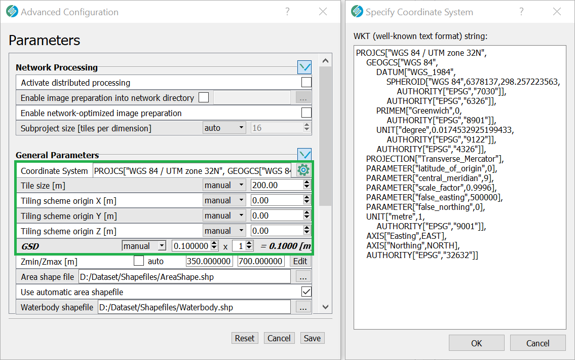
Interface for setting coordinate system, GSD, and Tiling
GUI
CLI
--coordinate-system path/to/coordinate_system.wkt
--gsd <output raster cell size>
--tile-size <tile size>
--tiling-scheme-origin <x> <y> or --tiling-scheme-origin-3d <x> <y> <z>