Mesh Converter Tool
SURE offers a Graphical User Interface that allows the conversion of *.osgb Meshes to several other formats.
Access from SURE GUI: Tools → Mesh Converter.
The CLI version (MeshConverter.exe) is documented here.
This tool can be used only if the SURE license contains the Meshing add-on.
Basic Usage
Input Mesh
This field takes the path to the input osgb Mesh. This can either be the 3D Mesh as the Mesh.osgb or the DSM_Mesh.osgb.
Important
This tool can read only osgb Meshes produced by SURE.
Output Folder
This field retains the path to the folder where the output Mesh will be written. The folder will be created if it doesn't exist beforehand.
Input Coordinate System
This field is necessary for the 3D Tiles and SLPK output formats. It takes the path to the file referencing the input coordinate system, in which the Mesh had been generated. This must be provided in a WKT (Well-Known-Text) format. Example:
PROJCS["ETRS89 / UTM zone 32N",
         GEOGCS["ETRS89",DATUM["European_Terrestrial_Reference_System_1989",
                 SPHEROID["GRS 1980",6378137,298.257222101,AUTHORITY["EPSG",
                         "7019"]],
                 AUTHORITY["EPSG","6258"]],
             PRIMEM["Greenwich",0,AUTHORITY["EPSG","8901"]],
             UNIT["degree",0.01745329251994328,AUTHORITY["EPSG","9122"]],
             AUTHORITY["EPSG","4258"]],
         UNIT["metre",1,AUTHORITY["EPSG","9001"]],
         PROJECTION["Transverse_Mercator"],
         PARAMETER["latitude_of_origin",0],
         PARAMETER["central_meridian",9],
         PARAMETER["scale_factor",0.9996],
         PARAMETER["false_easting",500000],
         PARAMETER["false_northing",0],
         AUTHORITY["EPSG","25832"],
         AXIS["Easting",EAST],
         AXIS["Northing",NORTH]]
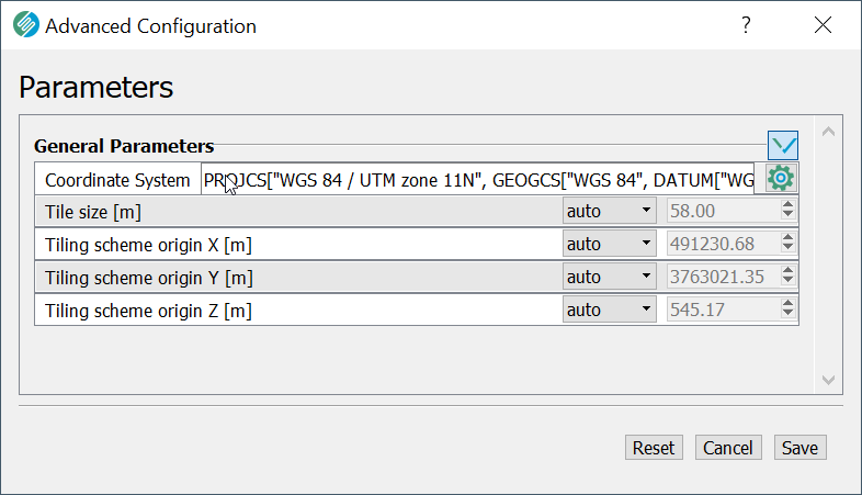
Project Area and Tiling Settings
These settings are only necessary for conversion to OBJ / DAE output formats (non-LOD). They are accessible through the Advanced Configuration button and can also be automatically loaded from an existing SURE Project.
Vertical Shift (optional)
Provided in project units, the default value is 0. This may be necessary only for the 3D Tiles and SLPK formats, in case the model's height is not correct, as it was imported from the input coordinate system. Can be used by users that have orthometric heights in the 3D Tiles Mesh as a way to visualize the Mesh in a 3D Tiles viewer at the correct height. See also 3D Tiles or SLPK: incorrect vertical model position
3D Tiles: Over-impose heights on the target ellipsoid
If this option is activated, the height values of the input Mesh will be interpreted as heights above the 3D Tiles ellipsoid. Therefore, the exported Mesh is over-imposed on top of the 3D Tiles ellipsoid in the 3D Tiles viewer. For example, if the aerial triangulation is in a datum referring to a geoid like DHHN2016, the exported Mesh will numerically still have the DHHN2016 heights in the 3D Tiles viewer.
If not activated (default), the height values of the input Mesh will be converted to the ellipsoidal heights used in the 3D Tiles viewer (WGS84).
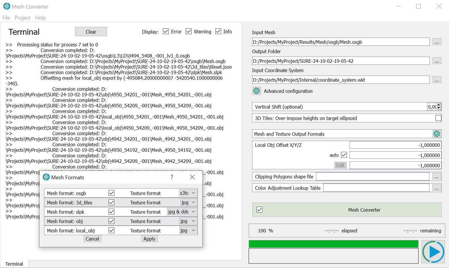
Mesh Format
The format of the output Mesh. Possible choices: 3D Tiles, SLPK, OBJ, LOCAL OBJ
See also output formats.
Texture Format
The format in which the texture atlases are stored.
Supported combinations of mesh formats ↔ texture formats:
Mesh format | Texture format |
|---|---|
3D Tiles | jpg |
SLPK | jpg / jpg and dds |
OBJ | jpg / png |
Local OBJ | jpg / png |
Local OBJ export format
The Mesh Converter enables exporting .obj meshes shifted to local coordinates, more suitable for viewing/processing in 3rd party software.
This new option is activated by choosing mesh format local_obj.
The shift to local coordinates can be manually specified in the fields Local OBJ Offset X/Y/Z or left to its auto (default value), resulting in a coordinate system with its origin at the project area centroid. The specified offset will be added to the original global coordinates.
Clipping Polygons shapefile
If a shapefile with polygons is specified for clipping, only geometry intersecting with the area of those polygons will be exported.
Color Adjustment Lookup Table
A color lookup table (LUT) can be applied during mesh export to enhance textures. This option allows adjustments such as blue haze removal, color saturation or other corrections. The following mesh output formats support color adjustment via LUT: osgb, 3d_tiles, slpk, obj, dae, local_obj.
A LUT can be created in image processing programs like Adobe Photoshop, GIMP or similar software. It must be provided in .CUBE format to the Mesh Converter. Visit our tutorial on best practices for creating a color lookup table.