SURE Viewer and Editor
Mesh Input Specifications
The SURE Viewer and Editor can load, display and edit osgb Mesh models produced with SURE.
SURE Viewer Keyboard Control Keys
Key | Action |
|---|---|
t | Toggle texture |
w | Toggle Faces/ Wireframe / Points |
l | Toggle lighting modes |
* | Increase level of detail |
/ | Decrease level of detail |
Camera Stations
Introduced in SURE 3.0, the viewer also shows the camera stations by displaying their virtual image plane as a white rectangle with a blue border.
Camera stations corresponding to deselected images appear grey (due to restriction of the area during project setup).
Camera input specifications
In the standalone SUREEditor.exe, loading an *.ori files list, together with a Stereo_Models.npz will allow the inspection of the flight configuration, as well as the stereo models selection.
Shortcuts for interaction with cameras
Shortcut | Action |
|---|---|
CTRL + Mouse wheel | Scale camera's virtual image plane |
ALT + Double click | Show stereo model of clicked camera |
Right click | Open image taken by clicked camera in image viewer |
Camera configuration together with mesh (deselected images grey) | Stereo model selection (Base image blue and slave images green) |
|---|---|
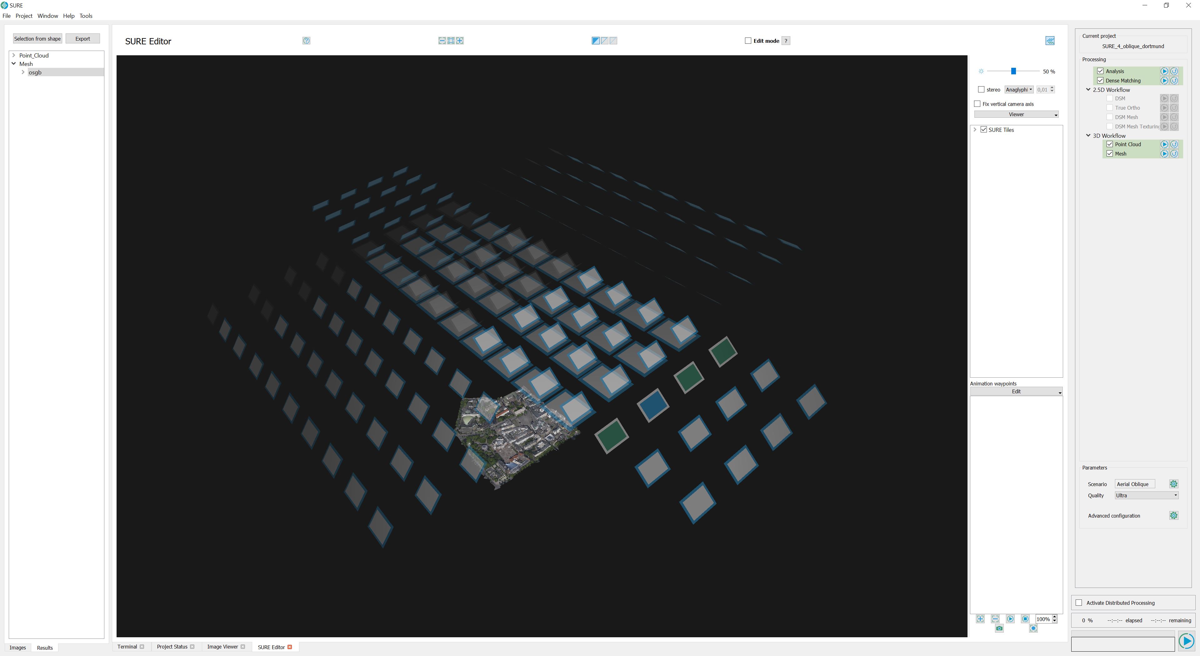 | 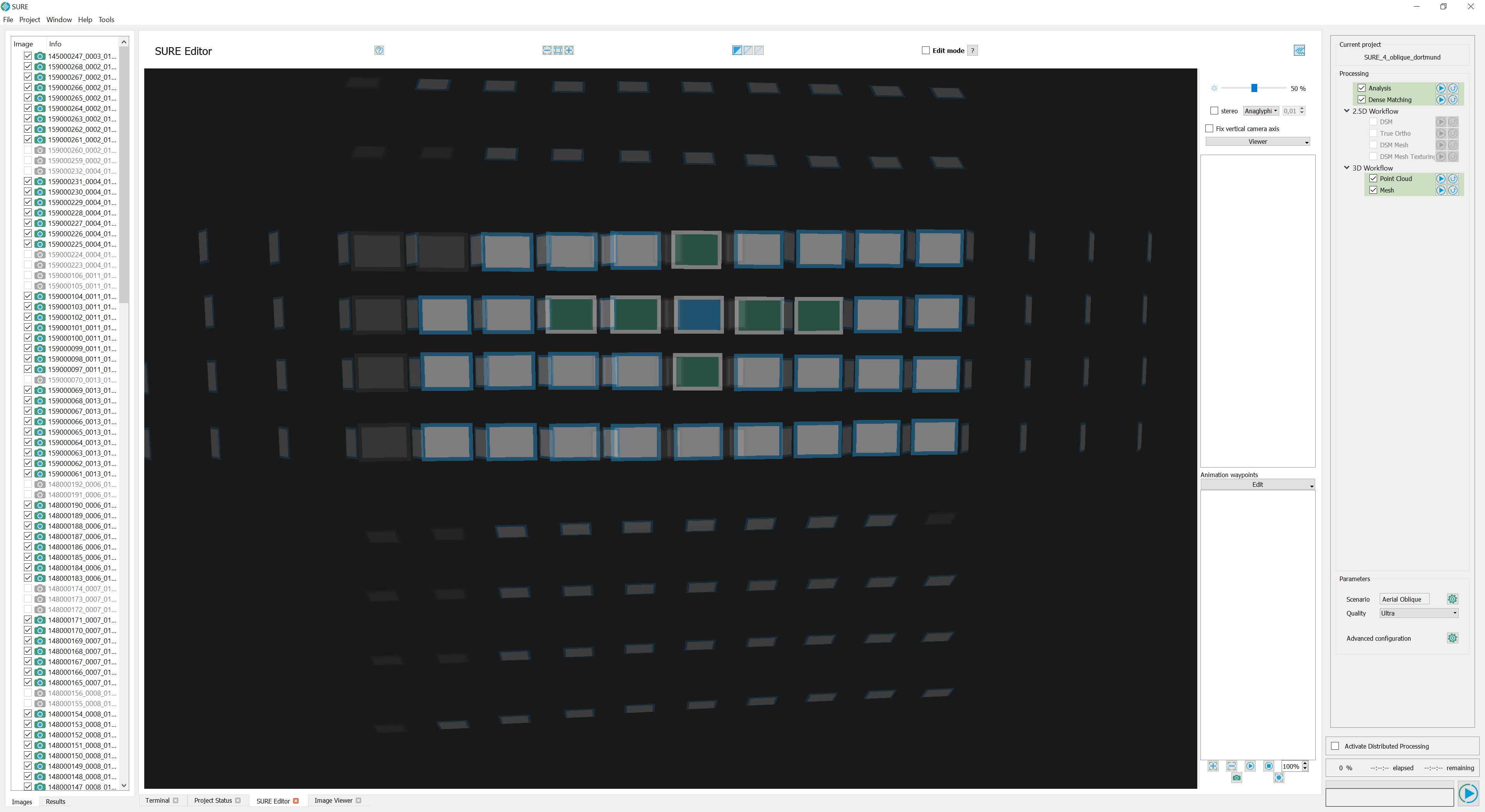 |
SURE Editor
SURE Editor extends the viewing capabilities of SURE Viewer and enables the user to interactively modify meshes.
Apart from editing meshes, the SURE Editor provides functionality to e.g. measure distances and get names of tiles and position coordinates.
For more details please refer to SURE Editor.
Bounding Box Visualization
The SURE Viewer can be used to visualize the bounding boxes of the individual tiles. Clicking the small arrow mark next to the main linking file reveals the list of all the Main_xx_xx_... files to which the former links. Selecting these in the list will display their bounding boxes, which can be useful to identify the tiles within the data set area.
Right-click on the selected tiles → Create linking file will generate a file that will link only to the specified tiles.
Especially for editing, a linking file grouping tiles into one unit is very useful, as loading this linking file automatically loads all relevant data of interest into the viewer and editor.
Complete Mesh with selection of tiles (bounding boxes) | Newly created linking file pointing to the selected subset of tiles |
|---|---|
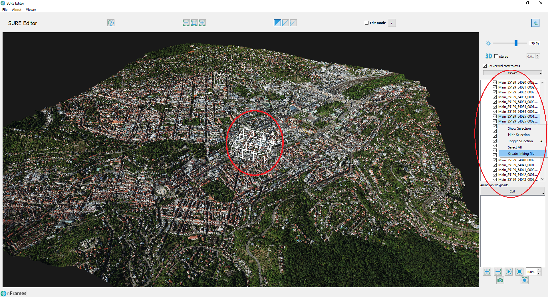 | 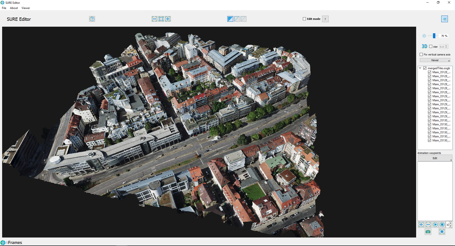 |
Right-click context menu
Highlight selected tiles
Hide and toggle mesh visualization
Create new main linking file to selected tiles (linking files are used to load several tiles at once).